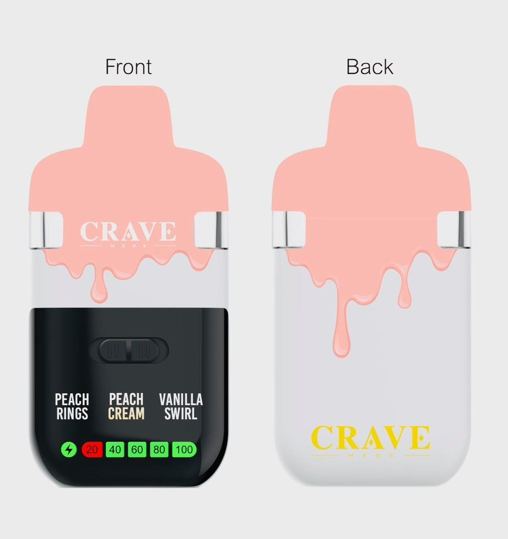

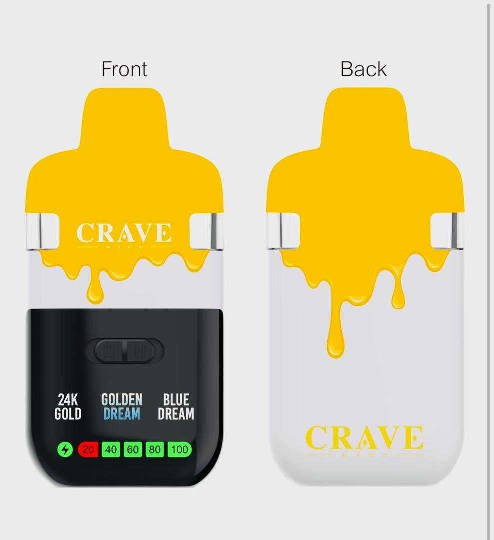
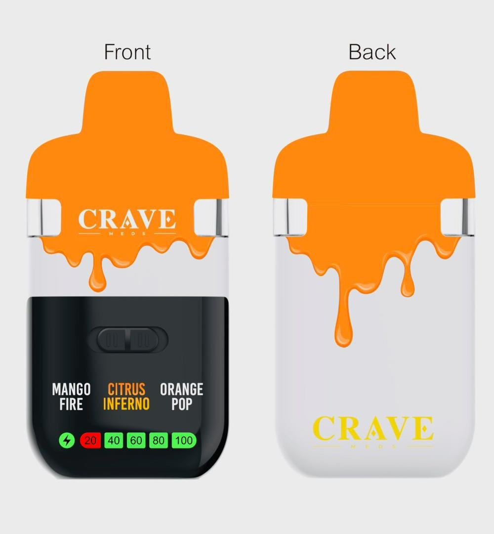
CRAVE MEDS 2G DISPOSABLE DUAL CHAMBER
Price range: $30.00 through $1,500.00
The CRAVE MEDS 2G Disposable Two-Chamber device is built on an unusual yet striking concept: two distinct internal environments operating side-by-side inside a single compact frame. Instead of relying on one reservoir and one heater, this device carries a mirrored internal layout that accommodates dual chambers, dual heating assemblies, and a synchronized electrical system designed to manage both sides with equal stability. As a result, the internal design feels more like a miniature piece of engineered architecture than a simple consumer product.
Description
Inside the Design of the CRAVE MEDS 2G Dual-Chamber Disposable — A Narrative Breakdown of Structure, Engineering, and Internal System Behavior
The Physical Story of the Dual-Chamber Chassis
The story of the CRAVE MEDS 2G Disposable Two-Chamber device begins with its outer shell, the part you hold but rarely think about. Although it looks simple from the outside, every curve, every seam, and every surface is the result of layered decisions made to support what happens internally. The device must feel balanced, withstand heat, tolerate pressure changes, and protect the delicate system hidden beneath the chassis. Therefore, its designers begin with the housing — the first and most visible chapter of the device’s construction crave meds 2g dual chamber.
1.1 The Shell’s Role in a Deeper Story
The exterior enclosure is crafted from durable polycarbonate or a polymer-aluminum blend, depending on the manufacturing run. In a narrative sense, this shell acts as the “body armor” of the device. It resists impacts, protects internal components from sudden temperature shifts, and maintains a rigid form even as the heating assemblies produce bursts of warmth beneath it.
Viewed up close, the housing reveals subtle curves designed to distribute physical stress. Pressing or squeezing the shell does not deform it, because the internal and external walls share a cooperative relationship: one provides the shape, and the other supports it from inside.
1.2 Beneath the Shell — The Internal Frame
Removing the outer layer unveils the internal skeleton, the actual structure that holds the dual-chamber configuration together. This internal frame looks almost architectural, with small beams, support ribs, and carved-out channels that guide components into precise positions. It behaves like a tiny blueprint brought to life — structured, intentional, and optimized.
The frame carries several responsibilities:
-
Holding the reservoirs in place
-
Preventing vibration or rattling
-
Maintaining exact spacing between heating assemblies
-
Providing airflow paths
-
Supporting the battery compartment
-
Housing the circuit board
-
Distributing mechanical load throughout the device
When you examine this layout, it becomes clear that the chassis and the frame are two halves of the same body, working in synchrony to manage internal forces.
1.3 The Dual-Reservoir Arrangement
The dual-chamber layout is the device’s defining feature, and the frame reflects that priority. Two reservoir compartments sit side-by-side, separated by a partition that behaves like a structural wall between rooms. This divider is not just physical — it is thermal as well. The partition blocks heat migration, ensuring one chamber’s temperature does not affect the other.
The seating pockets for each reservoir are shaped precisely. They use compression contours and reinforced base supports to prevent movement. Even when the device is shaken, dropped, or transported, the reservoirs remain locked in position. Over time, this stability ensures consistent performance.
1.4 The Supporting Players — Gaskets, Reinforcements, and Insulators
Because the internal components generate heat, the frame and reservoirs need added protection. Around the reservoir pockets and heating assemblies, heat-resistant silicone rings and insulation pads are installed. These act like lines of defense, guarding sensitive materials from thermal exposure.
Every piece, no matter how small, plays a part.
A gasket prevents a vibration.
A seal protects a compartment.
A buffer absorbs pressure.
Even the subtle foam pads embedded between certain components help stabilize the structure.
1.5 The Battery and Its Protected Position
At the center of the frame lies the battery housing — a compact, reinforced compartment designed to keep the power cell isolated from heat and direct pressure. Because batteries respond poorly to extreme temperatures, the designers include flame-resistant polymer walls and shock-dampening brackets. These ensure that the battery stays secure and operates safely.
The battery sits like the heart of the device, protected, insulated, and positioned to distribute weight evenly. Its placement contributes to the balanced feel of the device when held.
1.6 Airflow as a Structural Partner
Airflow is not only a functional requirement — in this device, it is a structural chapter of its own. The internal frame is molded with channels that move air through the device with minimal turbulence. These channels wind upward, splitting and merging until they join near the mouthpiece.
Because airflow shapes the activation of the device, these molded ducts must remain rigid. That is why they are reinforced with ribs and smooth interior surfaces, allowing the air to move freely without obstruction.
1.7 The Mouthpiece and the Final Interface
Above everything sits the mouthpiece, the final element in the structural story. It locks into the top of the housing through snap-fit rails or a compression seal. When installed, it completes the airflow pathway, guiding the blended output from both chambers toward its exit point.
The connection is engineered to prevent leakage, maintain pressure, and fit naturally into the aesthetic rhythm of the device. Once attached, the entire system becomes a single, cohesive structure.
The Electronic Narrative: How Power, Sensors, and Dual Heating Systems Work Together Behind the Scenes
Inside the CRAVE MEDS 2G Disposable Two-Chamber device, a hidden electronic ecosystem quietly manages everything that happens. Although the exterior structure tells a story of physical engineering, the internal electronic system reveals an entirely different narrative—a story built from current pathways, timed reactions, and coordinated circuitry. Every action the device performs comes from a sequence of decisions made at the circuit level, and each decision involves dozens of interacting parts. As a result, the device feels less like a simple tool and more like a carefully orchestrated electrical environment.
2.1 Where Power Begins — The Battery as the Device’s Silent Engine
Deep inside the device sits a lithium-based power cell, compact yet capable of delivering the current needed for two heating assemblies. While the battery remains hidden from sight, it plays one of the most important roles in the entire device.
You can picture it like a small engine resting in a protective chamber. It is placed in the center of the internal frame, partly for balance and partly for safety. Designers surround it with flame-resistant walls and insulation pads so that temperature fluctuations from the heating elements never reach its most sensitive areas. Additionally, the battery is clamped into place with shock-absorbing materials that prevent movement during impact or vibration.
Even though the battery never speaks, it drives the entire narrative. Without it, no sensor would activate, no coil would warm, and no airflow would create response. Every other electrical chapter traces its roots back to this one element.
2.2 The Printed Circuit Board — A Flat Landscape Packed With Decisions
Sitting above the battery, often tucked into a slender compartment, lies the printed circuit board, or PCB. If the battery is the engine, then the PCB is the command center—the place where electrical logic turns into coordinated activity.
From a narrative perspective, the PCB resembles a miniature city: copper pathways act like streets, components act like buildings, and electrical signals behave like travelers moving from one point to another. Furthermore, the PCB is designed with multiple zones, each handling a specific role.
These zones include:
-
the power-management district,
-
the dual-heating output sector,
-
the safety regulation block,
-
the sensor interface corridor, and
-
the grounding and stability plane.
Every zone depends on the others, much like a network of interconnected neighborhoods. Although the board is small, it performs constant calculations, checks, and adjustments every time the device activates.
2.3 The Microcontroller — The Thinking Component
At the center of the PCB’s “city” sits the microcontroller unit, or MCU. This tiny chip functions like the device’s brain, interpreting signals and issuing commands. It receives pressure readings, monitors electrical resistance, adjusts voltage flow, and makes sure both chambers receive stable power.
Narratively, the MCU works like a watchful guardian. It listens carefully for cues from the pressure sensor, paying attention to subtle differences in airflow. It tracks the status of each heating coil, identifying whether one chamber draws more power than the other. And because the device includes two separate heaters, the MCU balances their electrical demands with precise timing.
Additionally, the MCU uses a technique called pulse-width modulation. This allows it to deliver short bursts of power in controlled intervals, creating consistent heating without overloading the circuit.
Nothing the device does is random. Every action traces back to a calculation made inside this small piece of silicon.
2.4 Dual Heating Assemblies — Twin Engines Working in Harmony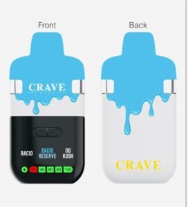
The CRAVE MEDS 2G device does not rely on one heating module but two, and this dual system adds both complexity and sophistication. Each chamber receives its own heating assembly, complete with internal coil, ceramic insulation, and metal support bracket. The heating elements behave like twin engines, warming in parallel yet operating under independent control.
The designers built each heating module with material choices that support durability under repeated temperature cycles. Therefore, the coils are typically made from alloys that tolerate expansion and contraction without weakening. Ceramic insulators surround these coils, guiding heat upward while shielding the rest of the device from exposure.
What makes the heating system interesting is the separation between the two modules. They do not share the same electrical path; instead, each has its own regulated channel controlled by the MCU. Consequently, the device can activate one chamber or both simultaneously without overstressing the internal electronics.
2.5 Wiring Pathways — The Electrical Highways Between Components
Connecting the battery, the PCB, the heating modules, and the sensor are thin wires designed to withstand heat, pressure, and movement. These wires wind through designated channels in the internal frame, almost like miniature highways that supply energy and communication across the device.
The wires are insulated with heat-resistant silicone so they do not degrade near warm components. Additionally, their routing is carefully planned, with curves, anchor points, and tension-relief pads keeping them secure. Although overlooked by many users, wiring is one of the most essential aspects of the device’s design because even a slight misalignment could disrupt the entire electrical system.
Viewed from above, the wiring network resembles a roadmap—simple at first glance, but deliberate in every angle and distance.
2.6 The Pressure Sensor — The Trigger Behind Every Activation
One of the most overlooked but significant components inside the device is the pressure sensor. This small module detects changes in airflow, signaling the MCU when to activate the heating modules. It responds to subtle shifts in pressure created during a draw, which means the airflow system and sensor must work in harmony.
Narratively, the pressure sensor is like a gatekeeper waiting for a cue. When air moves through the intake, it pushes against a small flexible diaphragm. The diaphragm’s movement creates a signal that travels to the MCU, telling it that airflow is present. Moments later, the device activates.
Additionally, the sensor is placed in a shared airflow chamber between the two internal routes. Therefore, both chambers can trigger activation with equal reliability. This careful placement contributes to the consistency of the entire system.
2.7 Safety Circuits — The Hidden Guardians of the Electrical System
Because the device handles dual heating loads, it includes several built-in protections to manage electrical safety. These protections consist of microfuses, surge-protection diodes, and over-current regulators placed at strategic points on the PCB.
In the narrative of electronics, safety components behave like silent guardians. They do not participate in normal operation, but they stand ready to intervene when something falls out of range. If a coil malfunctions, a wire shorts, or voltage spikes unexpectedly, these protective systems step in to prevent damage.
Their presence contributes to long-term stability, ensuring the dual-chamber architecture performs consistently over repeated use cycles.
2.8 The Coordinated System — Where All Electronic Elements Become One
When you view the electronic system as a whole, it feels like a coordinated digital ecosystem. Each component—battery, wiring, PCB, MCU, sensors, and heaters—cooperates through an invisible language of voltage and resistance crave meds 2g dual chamber.
Although the user may never see this internal choreography, the system performs complex decisions each time the device activates crave meds 2g dual chamber. And because of these layered interactions, the dual-chamber design functions smoothly without overwhelming the internal electronics crave meds 2g dual chamber.
The Airflow Narrative: How the Device Shapes, Directs, and Balances Two Independent Streams of Moving Air
When you look at the CRAVE MEDS 2G Disposable Two-Chamber device from the outside, nothing gives away the complexity of the airflow system operating within. Air enters through tiny openings barely visible to the eye, yet behind those openings lies a winding series of channels, tubes, and carefully structured interior spaces. These hidden passages determine how the device responds during use, and each one contributes to the rhythm of the internal system. Although the airflow design may appear simple, it behaves like a quiet mechanical story unfolding every time the device activates crave meds 2g dual chamber.
3.1 The First Moment of Movement — Air Reaches the Intake Ports
Every airflow journey begins at the intake ports located near the bottom edges of the device. These openings might look like small design choices, but they are precisely measured entry points engineered to maintain consistent pressure.
When air first slips through these ports, it encounters a smooth and angled surface molded directly into the internal frame. This angled surface helps guide the air along the correct pathway, reducing turbulence during the very first inches of travel. Because the device contains two chambers, the intake system is divided into two separate routes. This separation ensures that airflow enters each chamber cleanly without accidental crossover.
In this early stage, the air behaves like a traveler stepping into a doorway—quiet, unobtrusive, yet ready to move deeper into the device’s internal structure.
3.2 Two Paths, One Device — The Dual-Channel Airflow Layout
As soon as the air passes through the intake ports, the internal frame splits it into two independent channels, one for each chamber. These channels run parallel to each other, like two narrow corridors carved through the device’s interior.
Although they share the same starting point, they do not intersect. Each channel maintains its own:
-
width and diameter,
-
structural reinforcement,
-
internal surface smoothness, and
-
direction of flow.
Designers intentionally sculpted these channels to retain symmetrical shape. Even a small deviation between the two paths could cause one chamber to receive more airflow than the other, resulting in inconsistent activation. Because of this, both channels are built under identical tooling standards, ensuring every device maintains predictable airflow patterns.
3.3 The Pressure Sensor’s Chamber — Where the Airflow Narrative Changes Direction
Once the air moves several centimeters inside the device, both channels curve upward and feed into a shared sensor chamber. This chamber represents the first moment of contact between the two separate airflow paths. However crave meds 2g dual chamber, rather than mixing the streams, the chamber simply gathers pressure information.
Inside this area, the pressure sensor waits like a silent observer. As air enters the sensor cavity, it compresses a flexible diaphragm crave meds 2g dual chamber. The diaphragm’s movement becomes the signal that travels toward the microcontroller. This moment is crucial because it determines whether the heating modules activate crave meds 2g dual chamber.
Narratively, this chamber feels like an intersection crave meds 2g dual chamber. Two paths converge not to blend, but to deliver a message. Once the message is delivered crave meds 2g dual chamber, the MCU signals the dual heating modules to begin their work crave meds 2g dual chamber.
3.4 Air Meets Heat — The Transformation Within Each Heating Module
After the airflow triggers activation, each channel continues upward, arriving at its own heating assembly. The design of this transition zone is essential for temperature stability crave meds 2g dual chamber. Therefore, the airflow path enters the heating section at a precisely aligned angle. This ensures the air interacts evenly with the heating coil crave meds 2g dual chamber, rather than hitting it at an inconsistent or disruptive direction crave meds 2g dual chamber.
Here, something important happens crave meds 2g dual chamber:
The air transforms crave meds 2g dual chamber.
It moves through coiled alloy heating elements enclosed in ceramic insulation, absorbing heat rapidly as it travels. This section of the pathway is built with heat-resistant walls to prevent deformation. Additionally, the internal surfaces are polished to maintain smooth movement even as temperatures rise.
Each chamber conducts this transformation independently. One airflow path warms and accelerates, while the other does the same only inches away. Although they remain separate, they follow mirrored behavior.
3.5 Vapor Channels — Two Streams Moving Toward a Shared Destination
Once heated, the air becomes vapor. This new vapor flows into two dedicated vapor channels that sit above the heating modules. These channels are built from materials capable of resisting thermal expansion. Consequently, they maintain their shape even after repeated heating cycles.
The channels act like long hallways. They guide the vapor upward without sharp corners or sudden constrictions. Because vapor is more delicate than air, the interior surfaces must remain as smooth as possible to prevent turbulence crave meds 2g dual chamber.
Additionally, each vapor channel includes:
-
structural ribs for reinforcement,
-
extended length for stabilization crave meds 2g dual chamber,
-
gradual tapering to maintain velocity, and
-
heat-resistant coatings to preserve shape crave meds 2g dual chamber.
These channels protect the vapor’s momentum and ensure it arrives properly at the next destination crave carts.
3.6 The Convergence Chamber — The Device’s Internal Meeting Point
Eventually, the two vapor channels approach one of the most important architectural features of the device: the convergence chamber crave meds 2g dual chamber. This is where the previously independent vapor streams meet.
Unlike the pressure-sensor chamber, where air enters briefly and exits quickly, the convergence chamber is designed with more complexity crave meds 2g dual chamber. Its interior shape resembles a dome or hollow bowl, depending on the production variant. Because of this shape, vapor entering the chamber spreads and stabilizes before merging crave meds 2g dual chamber.
Narratively, this chamber is the heart of the airflow system. Two paths come together and become one, yet they do so gently, without forcing pressure spikes or uneven mixing. The rounded interior walls guide vapor smoothly toward the mouthpiece channel crave meds 2g dual chamber.
Additionally, designers include subtle contours inside the convergence chamber that balance the pressure between both paths. This ensures neither vapor stream overpowers the other.
3.7 Climbing the Final Path — The Main Output Channel
After merging, the vapor travels through a single output channel leading to the mouthpiece. This channel is taller, narrower, and more streamlined than the earlier sections. Its purpose is to maintain consistent flow heading upward.
To achieve this, the output channel integrates:
-
aerodynamic shaping,
-
structural reinforcement braces,
-
polished interior walls, and
-
a tapered exit near the mouthpiece.
Because this final segment guides the combined flow from both chambers, its geometry must remain as rigid and predictable as possible crave meds 2g dual chamber. Even small distortions could disrupt the balance of the vapor.
3.8 The Mouthpiece — The Last Component in the Airflow Story
The journey concludes at the mouthpiece. Although the mouthpiece appears simple from the outside, its interior includes a final-stage airflow guide that straightens the flow before it exits crave meds carts.
This guide includes:
-
narrow internal ribs,
-
condensation-resistant shaping, and
-
a subtle expansion chamber to stabilize pressure.
The mouthpiece locks into the device using rails or compression seals. Once in place, it completes the entire airflow ecosystem crave meds 2g dual chamber.
3.9 The Complete Airflow Story — A System Built on Balance
When you look at the entire airflow system—from intake ports to mouthpiece — you can see how each component plays its part in a larger narrative crave meds 2g dual chamber. Air enters gently, divides cleanly, triggers activation, transforms through heat crave meds 2g dual chamber, and then converges again with precision crave meds 2g dual chamber.
Nothing about this pathway is accidental crave meds 2g dual chamber.
Every angle, every surface, every curve represents a deliberate engineering choice crave meds 2g dual chamber.
Together, these choices create a stable environment where air moves predictably and efficiently through the dual-chamber design, allowing the entire system to function exactly as intended crave meds 2g dual chamber.
Related products
-
Sale!

NEW GRAB & DAB 2G DISPOSABLE
Price range: $25.00 through $1,500.00Select options This product has multiple variants. The options may be chosen on the product page -
Sale!

OMAKASE LIQUID LIVE DIAMONDS 2G DISPOSABLE
Price range: $25.00 through $1,250.00Select options This product has multiple variants. The options may be chosen on the product page -
Sale!

CLEAN CARTS 2G DISPOSABLE TIFFANY EDITION
Price range: $30.00 through $1,500.00Select options This product has multiple variants. The options may be chosen on the product page -
Sale!

NEW FAVORITES MINIS 2G DISPOSABLE
Price range: $30.00 through $1,250.00Select options This product has multiple variants. The options may be chosen on the product page
Reviews
There are no reviews yet.